

The Evolution of Aerodynamics in Race Cars
The art of manipulating flow around race cars to make them faster has evolved over the past few decades from something that gives a team an advantage over the competitor, to a game-changer, setting the most important trends in the design of race cars.
Without understanding aerodynamics, a team is out of the race. On the contrary, the teams which can master even the smallest details of the flow field and use them to increase performance are the ones who can truly vie for victory.
Impact of Aerodynamic Features
A single aerodynamic feature can alter not only the flow field in its immediate vicinity, but also propagate its effect further downstream, disrupting the existing vortices, and bringing huge impacts in the overall picture.
This is especially true for parts in the front of the car interacting with clean incoming air where the biggest portion of energy is still available. An example of a tiny element causing various effects in the global flow field around a Formula 1 car are nose guide vanes.
Nose Guide Vanes: Function and Evolution
As shown in the image above, nose guide vanes are aerodynamic devices located under and on the sides of the car’s nose. They are used to create a vortex system with the flow coming from the front wing, mainly with a Y250 vortex. It has multiple functions:
- Directing vortex under the car’s floor and therefore creating more front floor downforce
- Directing the wheel wake outboards, helping the rear wheel wake control
- Ensuring proper function of Y250 in a range of operating conditions, especially in terms of yaw angles
- Making the car less yaw-sensitive and therefore increasing the overall downforce though cornering conditions
The feature was introduced in the 2000s from nose-hanging skirts. Relatively simple components evolved into sophisticated multi-elements, creating a complex system with barge boards, until 2019 when they became restricted by new regulations. In 2022 they were completely banned.


(image source: Giorgio Piola)

Computational Fluid Dynamics (CFD) Study
Differences in performance can result from smaller changes to an aerodynamic part as well.
The following CFD study shows how the horizontal position of the guide vanes impact the flow field around the car. The study was carried out using the geometry of Ferrari SF16H (2016), which can be seen below.
The CFD simulation was run in Bramble CFD software on a symmetric ½ CAD model. The detail of the guide vanes shape can be seen here:


Fig. 3: Ferrari SF16H and its nose guide vanes (maxf1.net)
The aim of this study was to show the impact of the nose guide vane position, so the design of the part itself remained unchanged.
Apart from the baseline (original position), two variants were considered: the vanes were moved in the x-axis negative direction by 50mm and 100mm, as illustrated here:

Effects of Changing Guide Vane Position
Changing the position of one single part by 10 centimetres on the 3.5-meter-long car doesn’t sound very significant, does it?
Actually, this change can make a difference. As shown in the CFD results below, variations in the flow field far away from the nose guide vanes itself are seen. The change is powerful enough to effect the direction of the front wheel wake, influence the flow around bodywork and even impact the rear wheels and diffuser area of the car.

Detailed Flow Analysis
Tracing the origin of the change, let’s focus on the flow directly around the nose guide vanes.
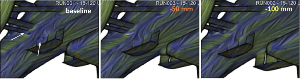
The flow in this area is massively impacted by the presence of front suspension. Although this element is aerodynamically optimized (cross sections of the suspension rods are airfoil shapes), it causes downwash, and separation behind it are still not unusual just as we see it on baseline.
Vortical structures and separation are present here on the guide vane element as well. Surprisingly, this can be easily suppressed only by a slight change of position. The middle plot shown in the images below is proof that even 50mm is enough to effectively get rid of it.
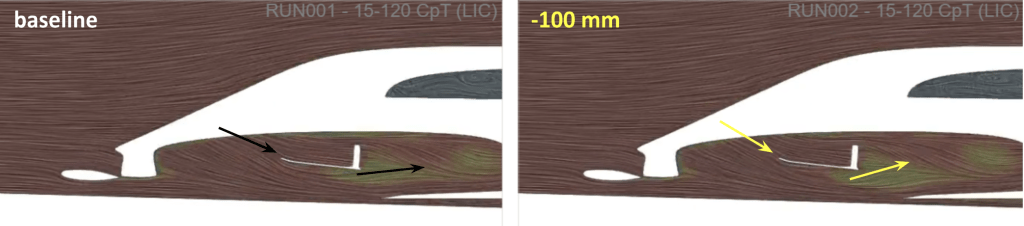
Another region where separation is present and unwanted is at the nose of the car. An effective way to mitigate this separation can be by moving the guide vanes as well. As shown in here, the region of separation becomes gradually smaller as the nose guide vanes move forward:

Separation also takes place on the leading edge of the nose guide vanes. The more forward their location, the steeper the angle of attack, and the more separation occurs not only on the leading edge but similarly behind the vanes.
However, this change in position induces more upwash at the same time, which means that the positive consequences of such a movement outweigh the drawbacks, as will be elaborated on further.
Impact on Downforce
The described change of the flow causes a significant change in static pressure, again, not only in the area of the nose guide vanes but also downstream. In the images above, it can be observed that the bigger upwash behind the more forward-located nose guide vanes leads to the altered angle of attack on the front floor and a different amount of stagnation here.
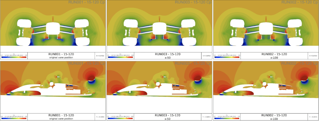
Following the effects caused by the presence of the nose guide vanes further, we observe significantly less separation in the area of the floor leading edge for more front nose guide vanes positions, and therefore the underfloor is fed with the air more effectively. It enables to generate more downforce not only with the front, but more total pressure is available also at the rear of the car.
The difference between baseline and moved vanes designs in terms of downforce is illustrated in Fig. 10. The more front the nose guide vanes, the more loaded the front floor and the lower static pressure regions occur.
Last but not least, a change of the nose guide vane position drives the front wheel wake away from the car which improves the tire management and overall efficiency in general.

Conclusions from the Study
The study revealed that moving nose guide vanes forward can potentially have multiple positive effects:
- Separation on the nose, front suspension and floor is mitigated
- More downforce is generated by the front floor
- With more energy available in the diffuser, more downforce is generated by the rear of the car
To continue this study, the next step would be running the simulations also for various yaw angles to confirm the expectation if:
- The range of yaw angles for which the guide vane creates a self-correcting effect on the Y250 position is wider
As was mentioned multiple times and demonstrated by the CFD study, the flow around the car is very complex, involving countless interactions of vortex structures and aerodynamic devices.
The effects created in certain positions prevail in the flow field and propagate further downstream. The whole system has to work in synergy, respecting the philosophy of the car and of course, current regulations need to be taken into account.
Inspired by Lucie’s insights? If you want to pursue a career as an Aerodynamicist, master Bramble CFD and Catia 3DX, our Aerodynamics Career Accelerator Program may be for you. Sign up down below for the next course today!

Check out Aerodynamics Career Accelerator Program!
Meet the Author

Lucie Zemanova holds an MSc in Mechanical Engineering Design and a PhD in Machines and Equipment from the Brno University of Technology in Czechia. Lucie has experience in the Automotive & Motorsport sectors, working as a Development Engineer. She has also served as a Track Marshall at Brno Circuit. Outside work, she enjoys playing football, go-karting, and reading. You can find Lucie on Linkedin here!
