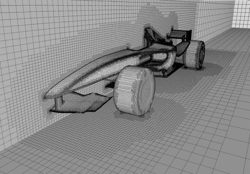
CFD has revolutionised car design execution, allowing engineers to simulate aerodynamic performance without costly wind tunnel testing. One of the steps in this process is creating a CFD mesh, which discretises the car’s geometry into small cells to solve the fluid equations. In this article, we oversee the power of CFD meshing in car design and guide you through the steps to generate a CFD mesh of a Formula 1 car.
Importance in Car Design
CFD meshing is immersed more than ever in car design as it directly impacts the accuracy and efficiency of the simulations. The mesh quality affects the reliability of the results, while the size affects the computational time required. In the case of a Formula 1 car, where every millisecond counts, a well-optimised CFD mesh can take performance levels through the roof.
Understanding the Basics
Before diving into the creation process, it is essential to understand the basics. A CFD mesh is a three-dimensional grid that represents the car’s geometry. It consists of a collection of small cells, each with its properties such as size and shape. These cells discretise the fluid equations and solve them numerically.
There are two main types of CFD meshing – structured and unstructured. Structured meshes are composed of regular-shaped cells, namely hexahedra or tetrahedra. Unstructured meshes, inversely, use cells of varying shapes and sizes. Each type has pros and cons, depending on the complexity of the car’s geometry and the desired accuracy level.
Creation Steps
The first step is to import the car’s geometry into the CFD software. In this case, there is a need to use CAD files like STEP or IGES containing the car’s surface geometry. Once imported, the content must undergo preparatory measures before it can be meshed. These involve tidying up the geometry, removing unnecessary elements, and ensuring it is watertight with no gaps or overlaps.
Next, define the mesh settings, such as the cell size and type. The size should base on the desired level of accuracy and the computational resources available. The cell type depends on the geometry complexity and simulation type performed. With the mesh settings designated, you can now generate the mesh. This process prompts dividing the car’s geometry into small cells according to the specified preferences. The software will automatically create the mesh based on predefined algorithms.
After generating the mesh, it is indispensable to check its condition. The mesh should have a well-balanced distribution of cell sizes, with no highly skewed or distorted cells. A lower mesh quality can lead to distorted results and convergence issues. If necessary, you can refine the mesh in areas of interest. For instance, it concerns increasing the cell density to capture fine details or regions with high flow gradients. Mesh refinement should come judiciously to evade computational costs.
Selecting the Appropriate Software
Performing precise and effective CFD meshing applications requires the right tool to achieve that purpose. The software selection process can cause some indecisiveness as there are plenty of options accessible, each possessing unique advantages and disadvantages. When making a decision, it is also important to evaluate factors like user-friendliness, compatibility with other simulation tools, and the availability of technical assistance.
The first option is ANSYS Fluent, a widely used CFD software offering advanced meshing capabilities. This solution has a range of options for structured and unstructured approaches, combined with an impressive array of features that allow users to manipulate and refine their meshes effortlessly.
OpenFOAM is another open-source software with a strong focus on CFD meshing. It delivers a selection of meshing algorithms and supports structured and unstructured meshes. The tool gives a high level of customisation, bracing the seamless integration of user-defined meshing techniques.
Lastly, STAR-CCM+ is a comprehensive CFD software that aligns further meshing capabilities with a user-friendly interface. This choice bestows a variety of meshing options, including polyhedral and Cartesian meshes, and provides automated tools for mesh generation and optimisation.
Optimisation Tips
Every CFD mesh optimisation commences with geometry simplification to reduce the mesh complexity. Be sure to remove any expendable details or features that do not affect the aerodynamic performance. Take advantage of the symmetry of the car’s geometry to decrease the computational domain. You can achieve considerable computational savings by simulating only an exact car extent.
Hence, conduct a mesh sensitivity analysis to determine the optimal cell size and type for the simulation. Vary the mesh settings and compare the results to identify the mesh settings that provide the best balance between liability and computational cost. Nevertheless, consider adaptive meshing techniques since they can dynamically refine or coarsen the mesh during simulation.
Advanced Techniques
With the aerodynamics performance in mind, some advanced techniques certify the mesh represents the complex car geometry, including the intricate details of the bodywork, wings, and tires. Boundary layer meshing is a go-to technique for aerodynamic optimisation. The boundary layer, located close to the surface of a car, guarantees precise capturing of this layer, and a mesh arises. This mesh consists of smaller cells near the surface and gradually increasing cells away from it.
Furthermore, mesh morphing allow you to deform the mesh to simulate moving components, such as the suspension or the wings. In Formula 1, this is particularly important, where the car’s geometry changes during different race stages. Ultimately, mesh adaptation methods dynamically adjust the mesh based on the flow conditions. With this, engineers can refine the mesh in regions of interest, such as the wake behind the car or areas with high-flow gradients.
Common Issues
Formula 1 cars have complex geometries with intricate details, such as wings, bargeboards, and diffusers. Capturing these details accurately in the mesh can be rigorous and may require advanced meshing techniques.
Maintaining a high-quality mesh is vital for accurate simulations. However, complex geometries and extreme flow conditions can lead to poor mesh quality, such as highly skewed or distorted cells. Addressing these issues requires careful mesh refinement and optimisation.
Therefore, creating a high-resolution mesh in such a demanding context can be computationally expensive. Balancing the desired level of accuracy with the available computational resources is a constant challenge.
Final Thoughts
CFD meshing is of utmost importance when enhancing car performance. It is crucial to accurately represent the car’s aerodynamic features through a well-optimised CFD mesh to gain valuable insights into its performance. In turn, this assists engineers in making informed design choices. Engineers in Formula 1 can elevate car design to unprecedented levels by combining cutting-edge software, optimisation techniques, and advanced meshing methods. This meticulous approach grants accurate and efficient CFD meshes while maintaining a professional and stellar standard.